keywords: 3D geometry; triangle selection; vertex selection;
When developing 3D software, you might want to allow the user to select specific polygons or vertices from your 3D model. Different parts of the geometry, such as corner points (vertices), triangles or surface normals must be selectable just by clicking on them. The complicated part is not only to calculate the right geometry entity which is currently selected by the mouse cursor, but also to do it fast enough. It must be possible to find the selected object in real-time to allow hovering. If the mouse is moved over the object, the software should give a visual feedback to the user by highlighting the currently hovered entity.
With the method presented here, you can implement a selection algorithm for the following 3D geometry entitites:
- Surface point
- Surface normal
- Vertices
- Edges
- Triangles
- Whole entities
One possibility to solve this issue is to calculate the solution manually using mathematics. By taking the current mouse cursor position and unprojecting it in 3D space using the inverse of the projection matrix and calculating the first intersection with a geometric entity, the solution can be found. However, this method is computation intensive, slow and cumbersome.

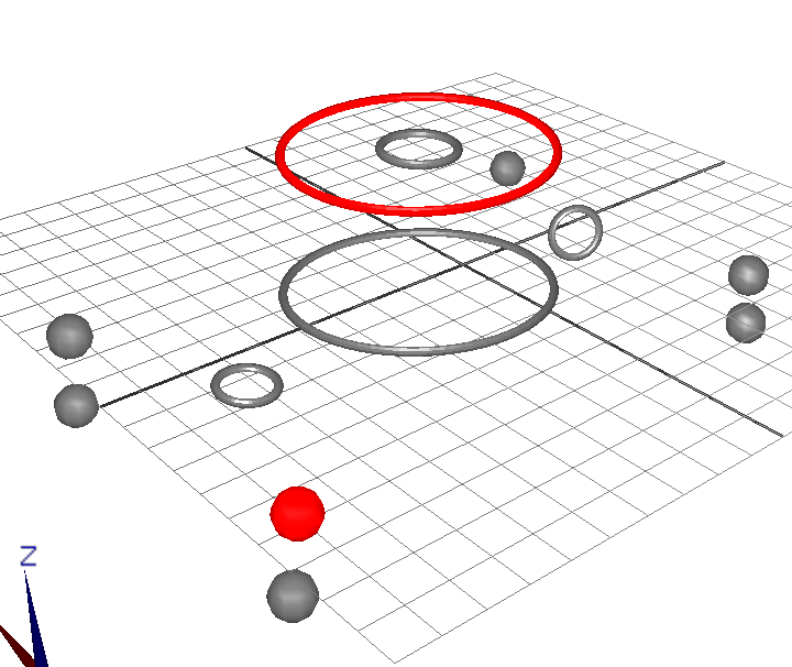
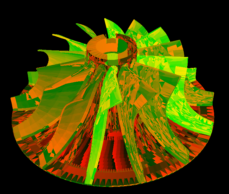
Luckily, it is not necessary to reinvent the wheel as already existing technologies can be used for this purpose. The OpenGL library supports rendering into back buffers, which means that the results are not visible to the user (off-screen rendering). To solve the problem of selection, the current view of the object is rendered into a back buffer using a special color coding method. In this selection rendering mode, lighting and geometry shading is disabled and the colors of the objects are defined by the programmer. Selectable objects are displayed in unique colors, while the background and non-selectable geometries are rendered in black. To find the geometric entity which is currently selected, a small part of the back buffer around the mouse cursor position is copied and the closest non-black color value is searched. The correspondence between the color code and the information of the selected element is determined by a lookup table. With this method, a hardware accelerated selection mechanism can be easily implemented. The picture above shows an image of this off-screen selection rendering. This method is sufficient for most geometric entities; however, some minor problems must be tackled with. If a vertex (a corner point of a triangle) is to be selected, it must be ensured that all vertices which are not visible due to occlusion, such as points on the backside of the object, are hidden. This is done by not only rendering the vertices with their unique color value, but also by rendering the whole geometry in the back buffer using black color. The depth-test of the video cards depth buffer will then automatically discard hidden points, making their selection impossible.
Another problem is to find the surface point on the geometry. In this selection mode, not the vertices of the triangle are to be selected, but the exact coordinates that are currently hovered by the mouse need to be known. While this case is less relevant for geometries with a dense triangle mesh, it becomes more important if the mesh is very sparse and only consists a few triangles. A large cube is an example of such geometry – due to the planarity of the surfaces, only very few triangles are necessary to generate the surface. To calculate the exact coordinates of the surface point currently hovered by the mouse, the color-keying method cannot be used. For this method, the solution is to render the geometry in the back buffer and then read the value of the depth buffer (z buffer) of the video card at the current mouse cursor position. This depth value can then be used to unproject the current surface point by inverse-multiplying the projection matrix and the extrinsic transformation to receive the coordinates of this point in the CAD model frame.